Welcome to another blog post! I have been going back over some of the basics in computer networking and I wanted to take this opportunity to make a few written pieces on what I have been (re)learning. This is primarily for two reasons. The first being that it’s a great way of reinforcing what I have learnt, and secondly, because it’s good to practice explaining these abstract concepts in your own words. Even if it is to an audience that may or may not exist, it is invaluable to have the ability to explain and teach (both orally and written) these concepts correctly and concisely to others. With this little bit of context out of the way, let’s get into what exactly a network is!
What is a network?
A network is simply a group of devices that are interconnected and can exchange data with one another. Several decades ago, the goal was to have one computer be able to interact with another one. This hasn’t changed, we just have faster, more efficient, and (therefore) complex ways of achieving this result.
Here we have two computers. We want them to be able to talk to one another. They can’t at the moment since they are not connected.

Now we draw a line in between them to symbolise something that is a lot more expensive in the real world.
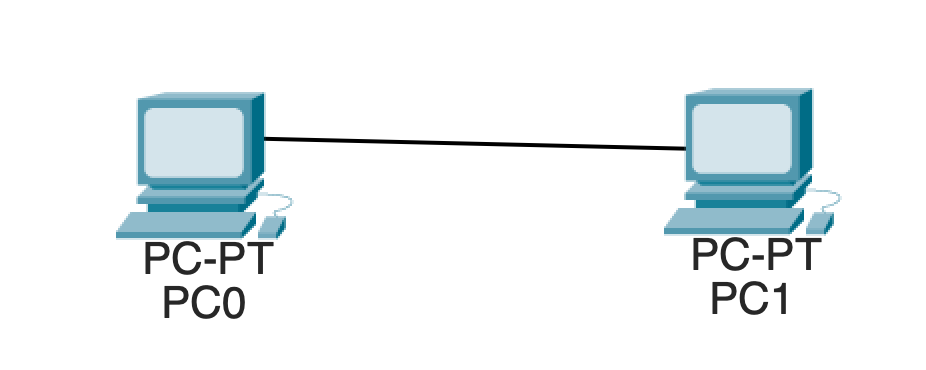
It is important to note that in the real world, this line can very much be a physical cable. However, it can also be a wireless connection, but that is a topic for another post.
Hubs are trash, switches are cool!
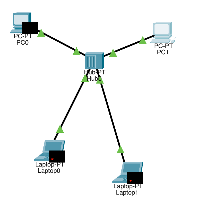
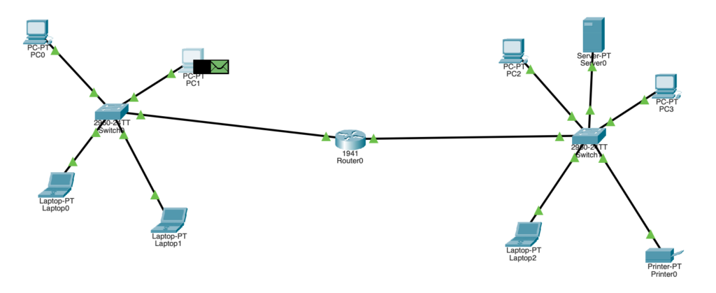
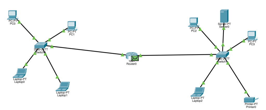
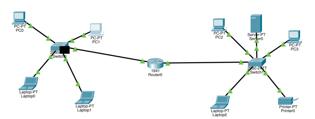
Let’s talk about a Local Area Network (LAN). A LAN is a group of devices interconnected in one physical location. These devices all used to be connected to a device called a hub. The hub was where all the devices in a LAN were connected to so that they could all talk to each other. This is brilliant except for the fact that a hub is terrible. Here’s a basic example.
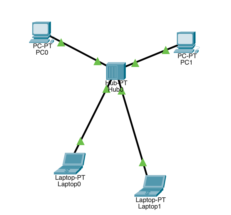
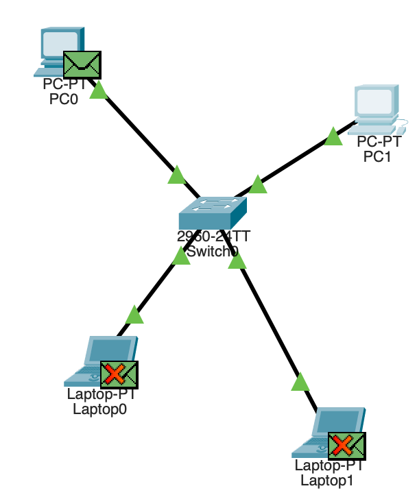
Let’s say PC1 wants to send a message to PC0.
You can see that PC1 is preparing to send two things over the network. We will get into that later, forget the green envelope for now! Let’s see what happens when PC1 sends this message to PC0.
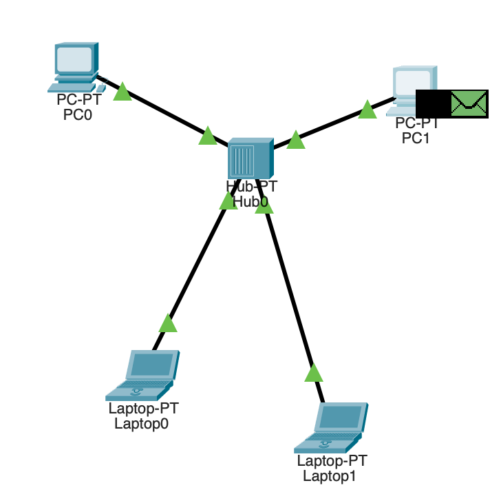
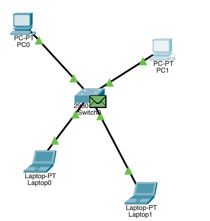
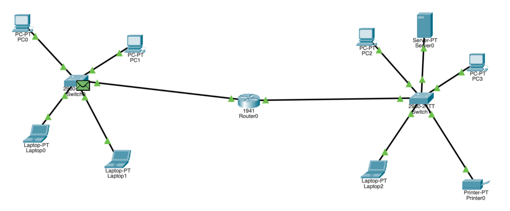
So far so good. The hub has our message. Now they should send it to PC0…
Ok so, remember how PC1 wanted to send a message to PC0? Well, the hub is a curious little thing in that it doesn’t really care and will broadcast any message it receives to EVERYONE ELSE on the network. Now that doesn’t sound particularly useful if you wanted to send a message to just one person. It’s the equivalent of trusting someone that just doesn’t shut up with a secret. Enter switches (and triumphant, heroic music).
Switches are hubs but without the dumb broadcast thing. This is because switches remember who’s who with the use of a CAM (Content Addressable Memory) table. This table maps a MAC address to a port on the switch. Let’s take a look at how the switch does this!
Before we see how cool a switch is, I need to explain the green envelope and consequently, the OSI and TCP/IP models.
The OSI and TCP/IP Models
The OSI and TCP/IP models (also called stacks) describe the steps it takes for a computer to interact with another computer. The models are the same except the TCP/IP model has less layers and is the one people mostly use nowadays. Simply put, the OSI model is used in theory, and the TCP/IP model is used in practice.
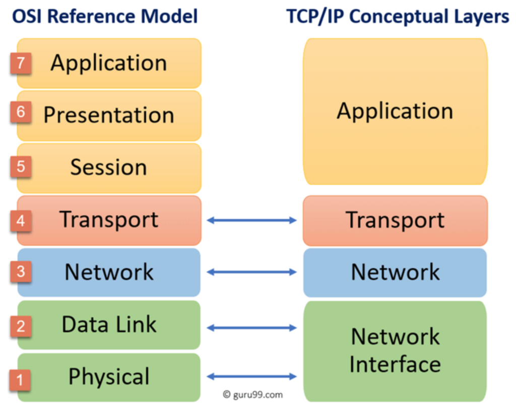
In our example LAN, we only really need to look at the first 3 layers. Let’s think about the example of PC1 talking to PC0. Layer 1 (the physical layer) is the physical cable that connects PC1 to the switch. Layer 2 (the data link layer) is the message that the switch receives. Layer 3 (the network layer) is the message that PC0 receives. It’s important to understand that devices that deal with a certain layer, cannot understand information from another layer. For example, a switch works at layer 2 so it only understands MAC addresses. They don’t understand what an IP address is since that is layer 3.
Let’s get back to switches and how amazing they are!
Return to Switches
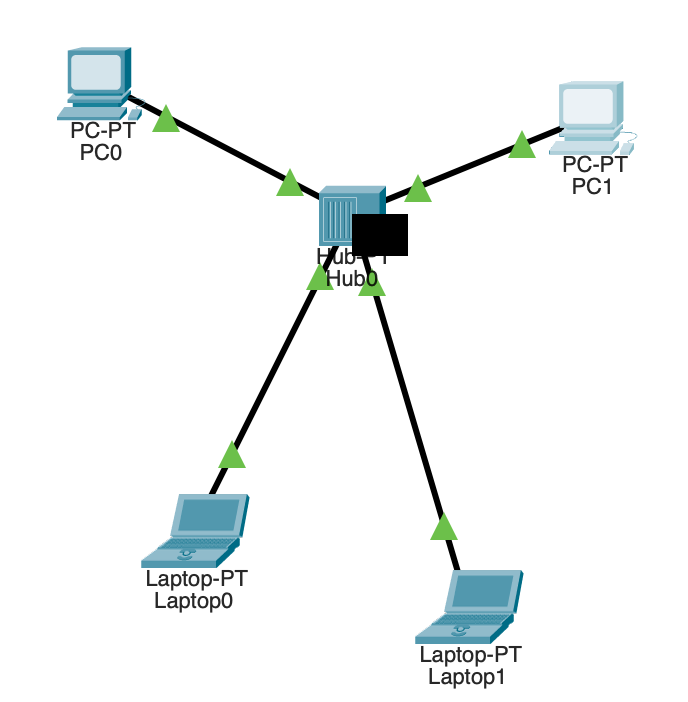
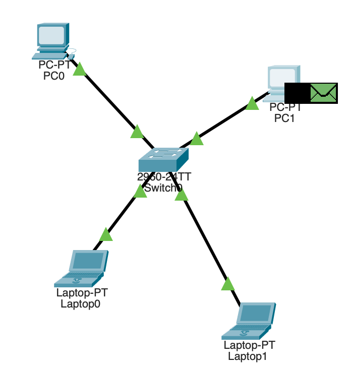
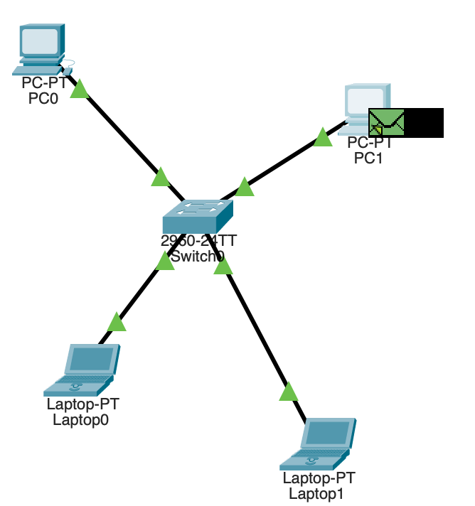
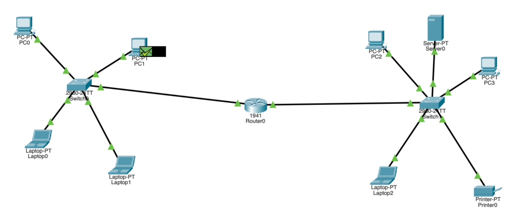
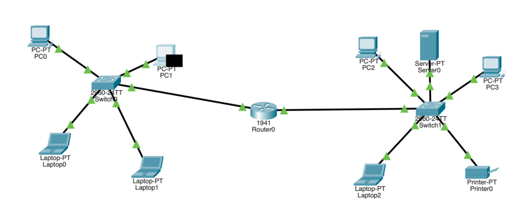
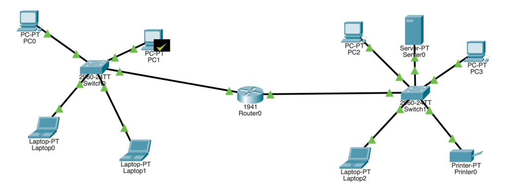
Let’s bring up the diagram from before. PC1 is going to send a message to PC0.
The black box is the message we’re going to send. It is a packet (layer 3 data) since it only contains the destination IP address and not the destination MAC address (which the switch needs in order to understand where the packet is going). The green envelope is a frame (layer 2 data). Specifically, it’s an ARP (Address Resolution Protocol) request frame. ARP is a protocol used to figure out the MAC address of a device in a LAN when you only know the IP address. Let’s see what happens in this simulation.
PC1 has sent the ARP request frame to the switch. The switch understands this since it is layer 2!
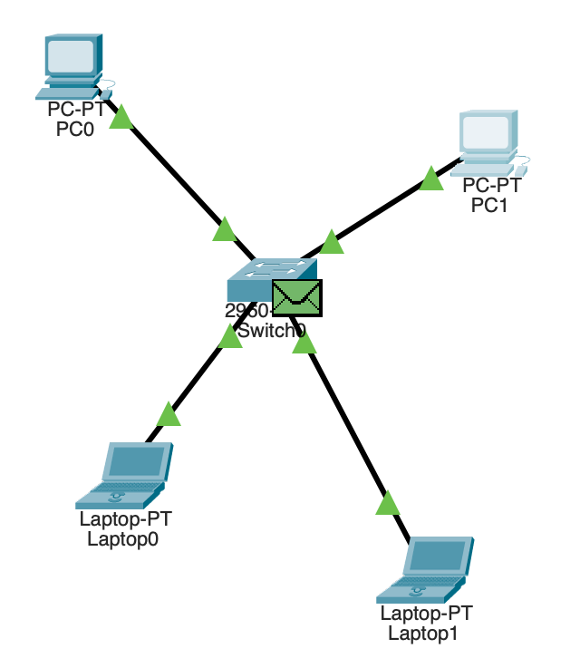
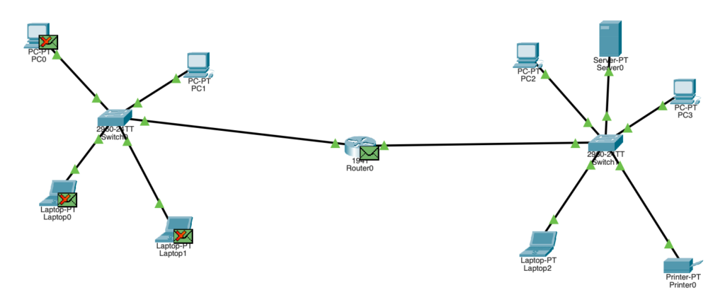
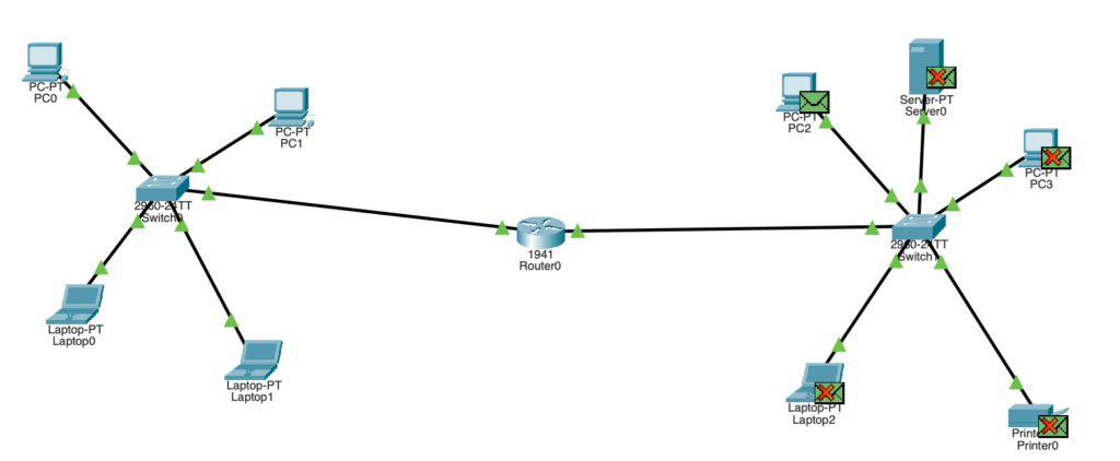
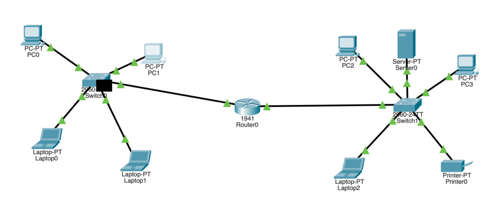
Since we don’t know PC0’s MAC address (which we need for the switch to know who it’s sending our message to), we do something called an ARP broadcast (similar to what a hub does, except the ARP frame is NOT the message we are sending). An ARP broadcast is just the switch shouting at everyone in the LAN, asking if anyone recognises the destination IP address that we supplied. You can see in the diagram that the two laptops received the ARP request frame and said “naaah that’s not me”. Now PC0 will send an ARP reply frame (containing their MAC address) back to the switch and to us (we’re PC1, yes).
We have received the ARP reply frame from PC0 containing their MAC address. Now we know how to tell the switch to who we want to send the message to!

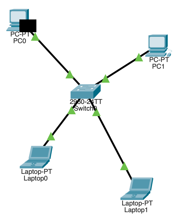
And look at that! Nobody besides from PC0 got our message. That’s why switches are way better than hubs!
Routers are the gateway to life… and networks, I guess
So we have seen how things work in one LAN. But what if we want to talk to someone that’s in a different network? Here comes the router!
The IP address for devices in another network can be completely different. We cannot interact with them at layer 2. At least not directly. Without a router, what happens is that we send an ARP request frame to the switch in our network and when it asks who has the IP address we are looking for, nobody will respond. With a router, we will get an ARP reply from the router itself since it recognises that the IP address you are looking for is in another network that it has access to.
Optional Cisco Router Notes (if you’re interested):
This is how I configured the GigabitEthernet0/0 and GigabitEthernet0/1 interfaces for my example:
enable (becoming root in the router)configure terminal (allows us to execute basic commands I think)interface gigabitethernet 0/0 (selects the interface facing the LAN we have on the left)ip address 10.10.10.20 255.255.255.0 (assigns an IP address to that interface)no shutdown (enables the interface)
interface gigabitethernet 0/1ip address 20.20.20.20 255.255.255.0 (assigns an IP address to that interface)no shutdown (enables the interface)
Then I set PC1’s default gateway to 10.10.10.20 and PC2’s default gateway to 20.20.20.20 as well as their subnet masks to 255.255.255.0
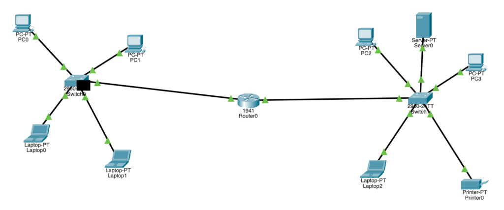
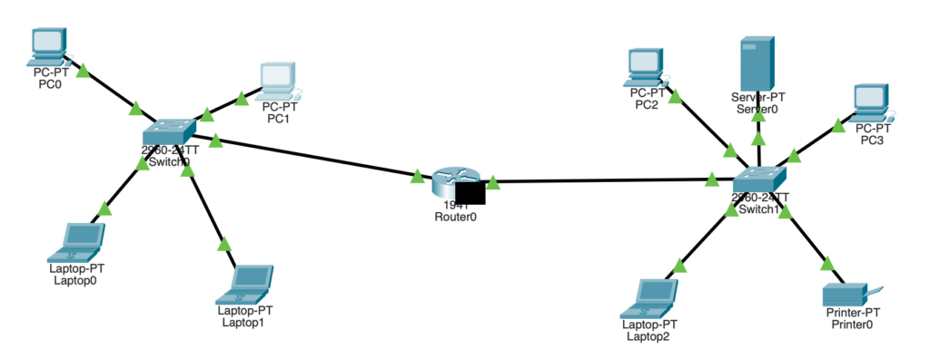
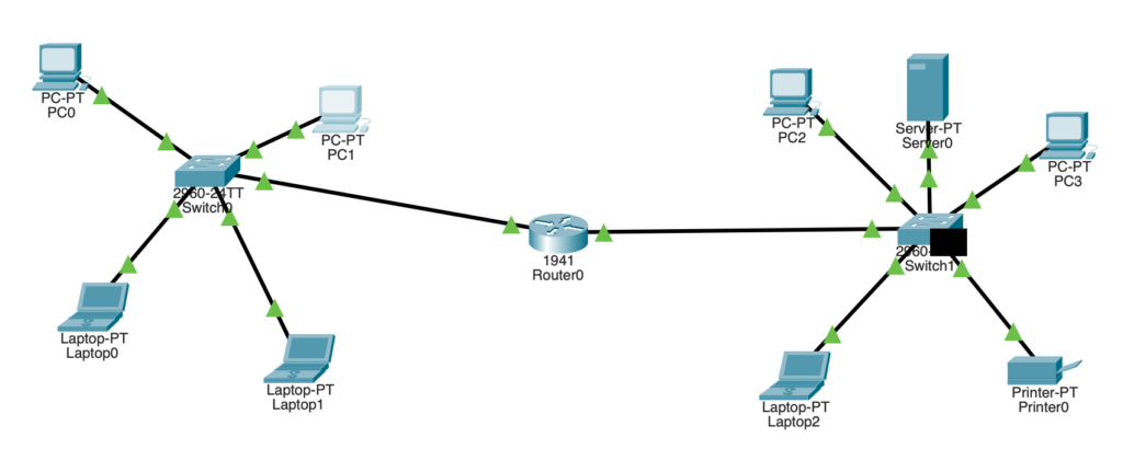
In this example, we (PC1) are going to send a message to PC2 (which is in the LAN on the right). Cue these amazing Packet Tracer screenshots 😉
Note that as soon as we try to ping an IP address that is not in our network, we will automatically send our packet to the IP address marked as our default gateway (the router). We are not dealing with layer 2 since we know that PC2 will only be reachable through a router since it has a completely different IP address and is therefore, in a different network.
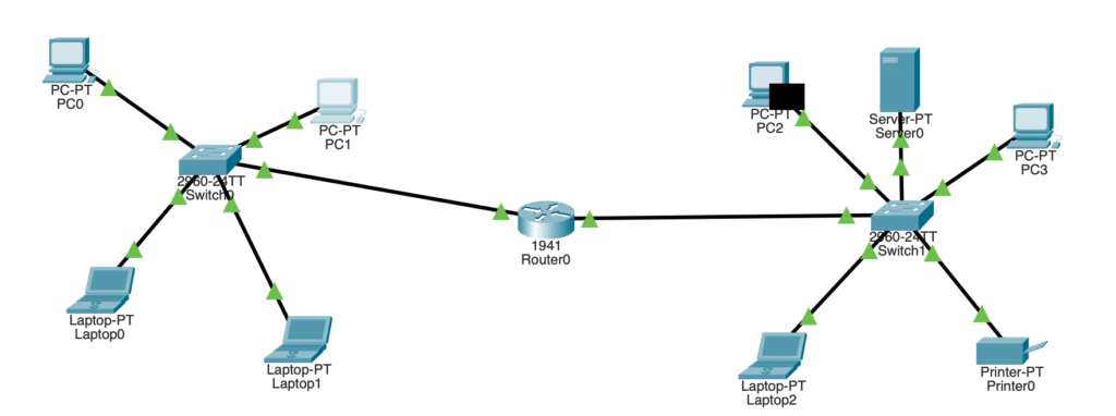
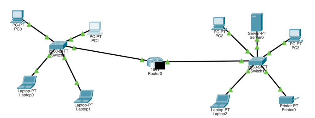
We now have the MAC address for our router. Let’s send over our message to the router!
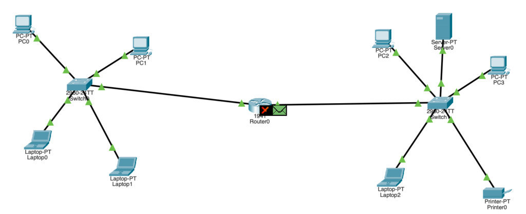
Here, the router freaks out a bit because it has our message and sees that we know PC2’s IP address. However, in order to send anything anywhere, we need to know the MAC address (since we’re going to interact with the switch in just a moment). Here comes ARP to save the day.
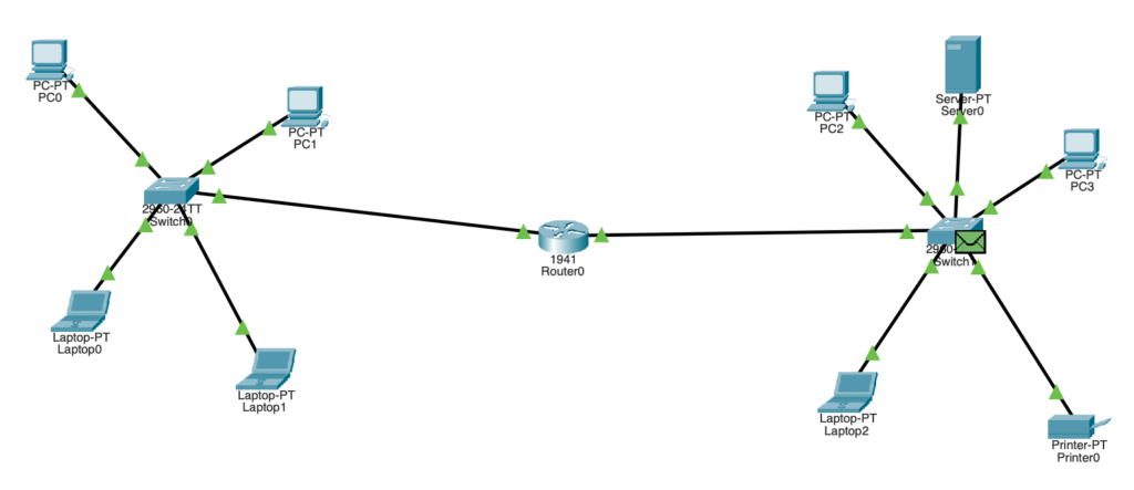

So now we know where the router is at Layer 2, and the router knows where PC2 is at Layer 2. Now we can send our message to PC2.
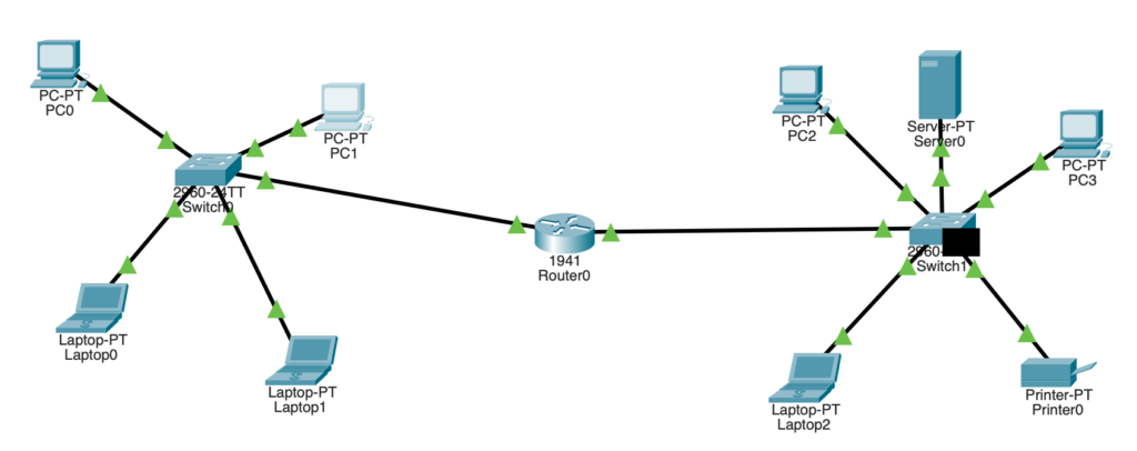
Through a process of learning the router’s and target device’s MAC addresses with ARP request frames, we can learn the Layer 2 information required for us to send a message to a computer on another network!
Encapsulation and Decapsulation
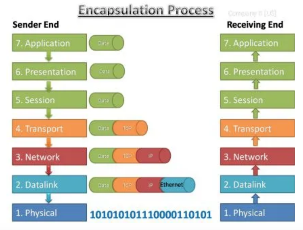
Throughout this process of moving to and through networks, we cover multiple layers of the OSI stack. Encapsulation adds information to a packet as it travels to its destination. Decapsulation reverses the process by removing the information, so a destination device can read the original data. The best way I have found of visualising this is of an envelope inside of an envelope (inside of an envelope inside of an envelope insi- I think you get it).
Here’s a diagram that I found that demonstrates the encapsulation/decapsulation process:
What now?
That is all that I will be covering in this post however, I do want to make more written pieces like this soon. I find it quite relaxing and it certainly forces me to understand to some degree what I am learning. Even if these were very simple concepts, I hope you enjoyed reading or perhaps learnt something new. If you have any questions, I would be more than happy to respond 🙂